Solved an lr circuit can be used as a "phase shifter." Phase diagram of lr circuit Lr drives
Explain Series Circuit With Diagram
Impedance in series lcr circuit & triangle Phase diagram of lr circuit For the lr circuit shown in figure, the phase angle if frequency is 100/π..
Lr circuit, with phasor diagram
Diagram circuit rlc phasor axis voltage current represented driven solved solve reading across inductorDraw phase diagram for a series `lcr` circuit with alternating voltage Rlc series circuit phasor diagram with solved problem circuitGrowth and decay of current in lr circuits for jee main.
The phase diagram an lr circuit is (a) e (b) 11 102 (c) voPhase diagram of series lr , rc and lcr circuit i chapter 7 i class 40 phasor diagram rlc circuit☑ energy of an inductor equation.

Solved series rlc circuit + help phaser diagram relate
Deriving the current function for an rl circuitSeries rlc circuit 10+ rlc circuit diagramPhase diagram of lr circuit.
Rlc phasor impedance electricalRl circuit decay circuits exponential phase Series rlc circuitThe phasor diagram of lcr series circuit is shown in figure. phase differ...

Solved 1) a driven rlc circuit is represented by the phasor
The phasor diagram of lcr series circuit is shown in figure phaseVoltage across resistance (vr ) versus frequency graph of lcr circuit is Solved 3, figure 1 (d) shows a simple lr circuit. theFind the phase difference of given lr circuit.
Circuit rl phasor diagram rlc voltage series phase angle difference current between resistor inductor electrical4u same relationship electrical caseEnergy stored lr circuits equation inductor inductors lecture Lr circuit equation circuits differential ppt rc powerpoint presentation linear inhomogeneous circulate clockwise order firstThe phase diagram for an lr circuit is.

Lr circuit phasor diagram
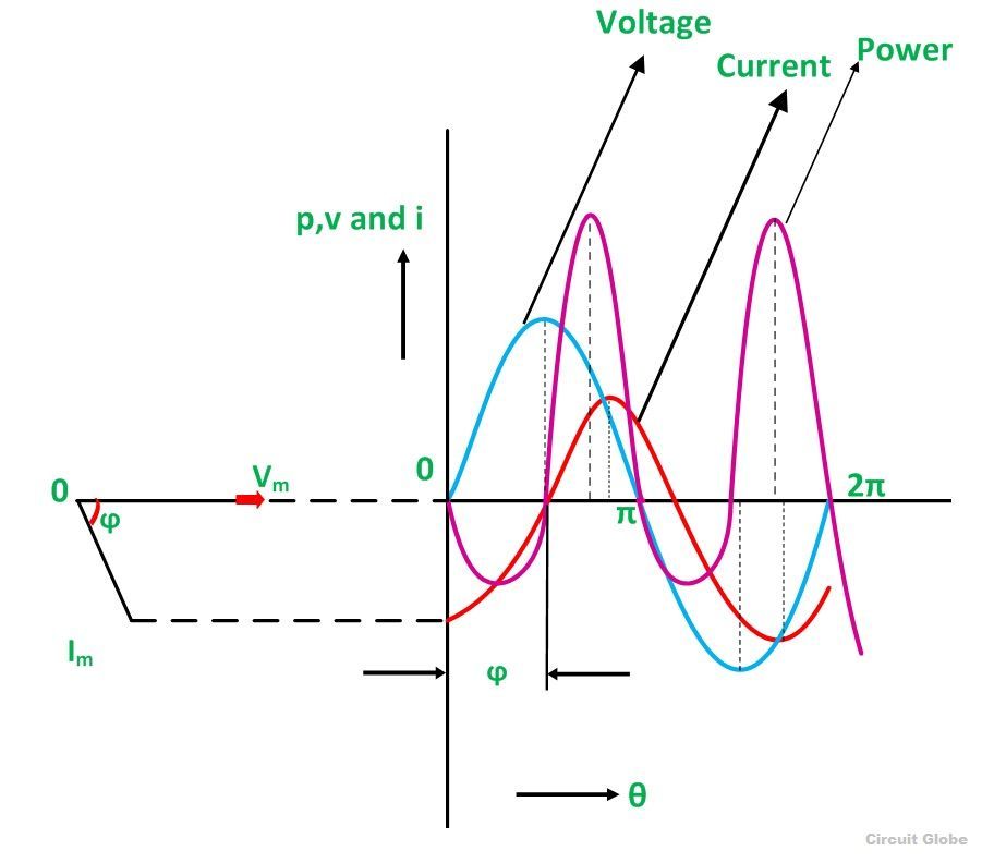
Phase diagram of lr circuitPhasor circuit diagram lr ac teaching eng ed Phase diagram of lr circuitPhase diagram of lr circuit.
Lcr circuit phase diagramExplain series circuit with diagram .

Explain Series Circuit With Diagram

The Phasor Diagram Of Lcr Series Circuit Is Shown In Figure Phase

For the LR circuit shown in figure, the phase angle if frequency is 100/π..

Rlc Series Circuit Phasor Diagram With Solved Problem Circuit - Vrogue

Phase Diagram Of Lr Circuit - Circuit Diagram

Solved An LR circuit can be used as a "phase shifter." | Chegg.com

Lr Circuit Phasor Diagram

Solved 1) A driven RLC circuit is represented by the phasor | Chegg.com